
Semiconductor Cooling
Maintain Optimal Efficiency in High Pressure Applications with the Madison FS8000 Flow Sensor
Integral parts of an overall control system
Flow Sensors in cooling towers for semiconductor wafer manufacturing are not standalone components.
Understanding Integration
Sensor Placement: Flow sensors are strategically placed within the cooling tower system. Common locations include the water inlet, outlet, and recirculation lines.
Signal Output: Flow sensors generate an electrical signal (usually a voltage or current) proportional to the flow rate. This signal is transmitted to the control system.
Controller Input: The control system (often a PLC or DCS) receives the flow sensor’s signal. It processes this data to determine the actual flow rate.
Setpoints and Alarms: Setpoints are configured based on desired flow rates. Alarms are triggered if the actual flow deviates from these setpoints (e.g., due to clogs or leaks).
Feedback Loop: Based on flow sensor feedback, the control system adjusts cooling tower parameters (fan speed, chemical dosing, or water makeup). For example: If flow decreases, the system may increase fan speed to compensate. If flow exceeds a threshold, chemical dosing may be adjusted. Flow sensors are not just about maintaining the right flow rate. They also contribute significantly to safety. In the event of a significant drop in flow, indicating a malfunction, the control system can promptly shut down the cooling tower, preventing any potential damage. This safety feature is a key aspect of flow sensors.
Integration with Supervisory Control and Data Acquisition (SCADA): In more extensive facilities, flow sensor data is often integrated into a SCADA system. Operators monitor and control cooling tower performance remotely.
MADISON’s Flow Sensors precisely measure the volume of liquids or gases flowing through a tube or pipe to maintain a specified flow rate. When the flow rate deviates from the required range, the sensor alerts the equipment or operator to act or disrupt the operation of the equipment (auto shut down) to prevent a potential issue or damage.
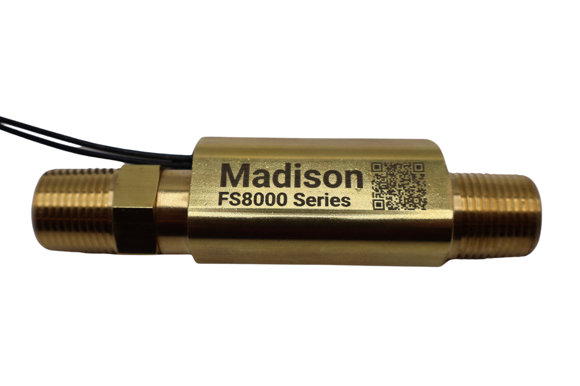
The robust FS8000 inline flow switch is the pinnacle of reliability and performance in high-pressure applications. Engineered to resist clogging and deliver reliable, consistent switching, the FS8000 showcases innovation through its one-piece magnetic Ryton® piston.
Tailored for high-pressure industrial cleaning equipment and cooling systems applications, it embodies the perfect synergy of straightforward design and unwavering operational dependability for discerning engineers. Low-pressure drop over the sensing range makes this the ideal solution for most applications.
Key FS8000 Attributes
Wetted Materials
- Housing/Body: 316 Stainless Steel
- Piston: Ryton R4
- Spring: 302 Stainless Steel
- O-Ring: Viton
- Epoxy
FS8000 Specifications
- Fitting type: 3/8” NPT or 3/8” Compression
- Flow Switch Points: 0.10 - 3.0 GPM
- Set Point Accuracy: +/- 10%
- Operating temperature: -20° to 275°F
- Max. pressure: 1500 psi
- Switch rating: 20-watt SPST, 120VAC/VDC, N.O.
- Recommended Filtration: 100 micron
- Approvals: UL recognition